Some time ago I did an investigation on if/how Unity can be used as a FX Composer replacement, using the free version as a test. I then concluded that to a large degree Unity could be used for shader prototyping. It was missing the low level access though that would allow me implement more complicated graphics techniques, so I jumped onto SharpDX for a couple years.
Developing code is good but sometimes you just need to drag and drop a few assets, attach a shader and get going. Now that Unity is available fully featured for free, it was time to give it another go. In this post I document my findings.
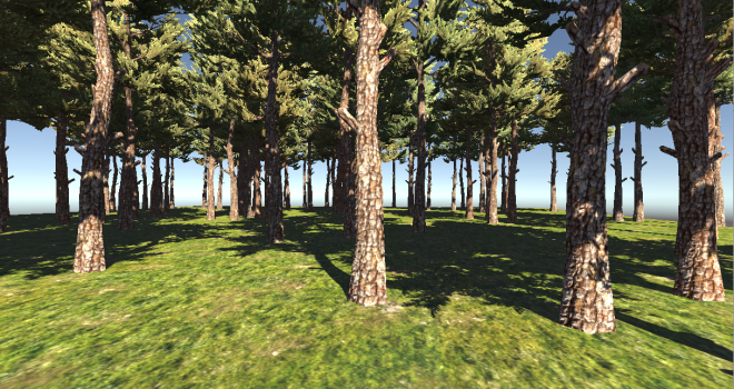
Since my work revolves around post processing effects a lot lately, I thought I’d start with that and try to implement a multi-step postprocessing effect as a test. I quickly put together a scene with a terrain and a few trees.
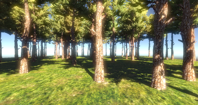
It turns out that it is very easy to use the standard post processing effects that come with Unity, all you have to do is drag a script onto the camera in the Inspector and you’re done. For example, import the Effects package and add Bloom.cs from the Image Effects folder to your main camera. Voila, our scene blooms nicely.
There is a large variety of post effects to try in the standard assets and it is worth doing so. Implementing our own post effect is a bit more involved though and documentation not overly detailed, especially for a newcomer.
Let’s start our custom post effect with something simple, one that tints the scene with a user specified colour. First a disclaimer, it is the first time I use Unity at such a low level and the information I’ve gathered is from the Internet and looking at existing code. In all probability there is a more efficient way of achieving the same effect.
A bare-bones post effect script looks something like this (C# is my language of choice with Unity):
using System;
using UnityEngine;

namespace UnityStandardAssets.ImageEffects
{
     [ExecuteInEditMode]
     [RequireComponent (typeof(Camera))]
     class SimplePostEffect : PostEffectsBase
     {
          public Shader TintShader = null;
          public Color TintColour;
          private Material TintMaterial = null;

          public override bool CheckResources ()
          {
               CheckSupport (true);

               TintMaterial = CheckShaderAndCreateMaterial (TintShader);

               if (!isSupported)
                    ReportAutoDisable ();
               return isSupported;
          }

          void OnRenderImage (RenderTexture source, RenderTexture destination)
          {
               if (CheckResources()==false)
               {
                    Graphics.Blit (source, destination);
                    return;
               }

               TintMaterial.SetColor("TintColour", TintColour);

               //Do a full screen pass using TintMaterial
               Graphics.Blit (source, destination, TintMaterial);
          }
     }
}
Our custom SimplePostEffect class derives from PostEffectsBase and has 2 public members, one for the shader (TintShader) to use with the effect and one for the colour (TintColour) that we will pass to the shader. The main method in this class is OnRenderImage() which will be called every frame after rendering of the main scene has been completed. The method receives 2 RenderTexture arguments, the source which contains the main scene rendered and the destination which will receive the result of our post effect pass.
Using the Shader object we declared in the class (TintShader) we create a Material object which will be used for the screenspace rendering. This is done in CheckResources(), which also performs some checks to ensure that the shader is supported by the selected platform.
The Blit() method of the Graphics object is the one that does the actual rendering, applying our material to the source texture. By the way calling Blit() without specifying a material will just copy the input to the output RenderTexture.
We are almost ready, all we are missing is a shader that will implement the post effect. Again, a bare-bones post effect shader looks something like this:
Shader "Custom/Tint"
{
     Properties
     {
          _MainTex ("", any) = "" {}
     }

     CGINCLUDE
     #include "UnityCG.cginc"

     struct v2f
     {
          float4 pos : SV_POSITION;
          float2 uv : TEXCOORD0;
     };

     sampler2D _MainTex;
     float4 TintColour;

     v2f vert( appdata_img v )
     {
          v2f o = (v2f)0;
          o.pos = mul(UNITY_MATRIX_MVP, v.vertex);
          o.uv = v.texcoord;

          return o;
     }

     float4 frag(v2f input) : SV_Target
     {
          float4 result = tex2D(_MainTex, input.uv) * TintColour;

          return result;
     }

     ENDCG
     SubShader
     {
          Pass
          {
               ZTest Always Cull Off ZWrite Off

               CGPROGRAM
               #pragma vertex vert
               #pragma fragment frag
               ENDCG
          }
     }
     Fallback off
}
It is comprised by a vertex and a pixel shader both very simple. Worth mentioning is _MainTex texture which has special meaning for Unity, Graphics.Blit() will look for it when it runs the shader and it will bind the source RenderTexture passed to OnRenderImage() above. Other than that the shaders are self explanatory, the vertex shader just transforms the vertices using the model view project matrix supplied by the engine and the pixel shader samples _MainTex and multiplies it by the TintColour shader constant.
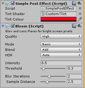
To apply the post effect, just drag the C# script we created above to the camera and assign the above shader to the “Tint Shader” field.
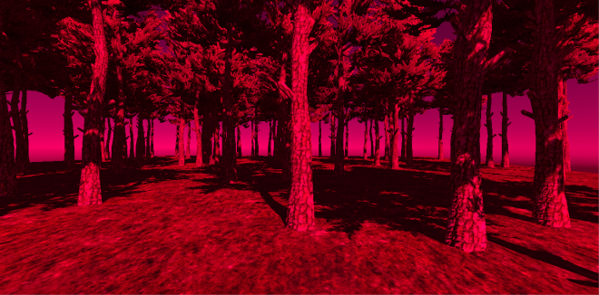
Then set a colour of your choice and marvel at the result! 🙂
What’s interesting is that you can easily combine post effects by adding more than one scripts to the camera.
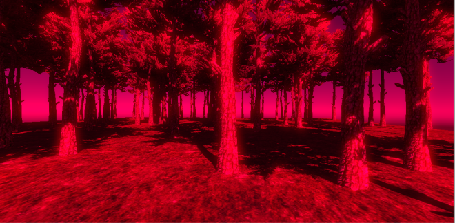
Here is our custom tinted scene that additionally blooms:
That was admittedly easy but post effects rarely rely just on the main rendertarget and a shader constant. We need more data such as scene depth, normals, and potentially the output of any rendering pass.
So I decided to push it a bit implementing volumetric lightshafts as a post effect. To do that, we need at a minimum the depth buffer and the shadowmap and also the ability to chain render passes to implement lightshaft blurring and applying to the scene.
Unity, when in deferred shading mode, provides access to the g-buffer rendertargets through global texture samplers:
_CameraGBufferTexture0: ARGB32 format, Diffuse color (RGB), unused (A).
_CameraGBufferTexture1: ARGB32 format, Specular color (RGB), roughness (A).
_CameraGBufferTexture2: ARGB2101010 format, World space normal (RGB), unused (A).
_CameraGBufferTexture3: ARGB32 (non-HDR) or ARGBHalf (HDR) format, Emission + lighting + lightmaps + reflection probes buffer.
Also we can have access to the depth buffer through the _CameraDepthTexture texture sampler.
The volumetric lightshafts technique that we implement is loosely based on Toth et al which is pretty standard in games nowadays. It is based on screen space raymarching calculating light extinction, in-scattering and occlusion at each sample. It is a fairly expensive technique so graphics programmers typically avoid computing it at full screen resolution, often choosing instead quarter resolution.
So the first step in our post processing pipeline would be to downsample the depth buffer. This a straight forward process, the shader that performs the quarter downscaling looks like this:
Shader "Custom/DownscaleDepth" {

CGINCLUDE

#include "UnityCG.cginc"

struct v2f
{
     float4 pos : SV_POSITION;
     float2 uv : TEXCOORD0;
};

sampler2D _CameraDepthTexture;
float4 _CameraDepthTexture_TexelSize; // (1.0/width, 1.0/height, width, height)

v2f vert( appdata_img v )
{
     v2f o = (v2f)0;
     o.pos = mul(UNITY_MATRIX_MVP, v.vertex);
     o.uv = v.texcoord;

     return o;
}

float frag(v2f input) : SV_Target
{
     float2 texelSize = 0.5 * _CameraDepthTexture_TexelSize.xy;
     float2 taps[4] = {     float2(input.uv + float2(-1,-1)*texelSize),
     float2(input.uv + float2(-1,1)*texelSize),
     float2(input.uv + float2(1,-1)*texelSize),
     float2(input.uv + float2(1,1)*texelSize) };

     float depth1 = tex2D(_CameraDepthTexture, taps[0]);
     float depth2 = tex2D(_CameraDepthTexture, taps[1]);
     float depth3 = tex2D(_CameraDepthTexture, taps[2]);
     float depth4 = tex2D(_CameraDepthTexture, taps[3]);

     float result = min(depth1, min(depth2, min(depth3, depth4)));

     return result;
}

ENDCG
SubShader
{
Pass
{
     ZTest Always Cull Off ZWrite Off

     CGPROGRAM
     #pragma vertex vert
     #pragma fragment frag
     ENDCG
}
}
Fallback off
}
A couple of things worth mentioning with the above shader, it use the Unity provided depth rendertarget _CameraDepthTexture. If you add the _TexelSize postfix to the texture name, you can also get the dimensions of the texture automatically, a really useful feature. The other thing worth mentioning is that you can’t downsample a depth buffer by averaging neighbouring samples, we have to use the either a min or a max operator.
Code-side, we need to create a quarter resolution rendertarget with a single 32 bit float format to store depth:
void OnRenderImage (RenderTexture source, RenderTexture destination)
{
     if (CheckResources()==false)
     {
     Graphics.Blit (source, destination);
     return;
     }

     RenderTextureFormat formatRF32 = RenderTextureFormat.RFloat;
     int lowresDepthWidth= source.width/2;
     int lowresDepthHeight= source.height/2;

     RenderTexture lowresDepthRT = RenderTexture.GetTemporary (lowresDepthWidth, lowresDepthHeight, 0, formatRF32);

     //downscale depth buffer to quarter resolution
     Graphics.Blit (source, lowresDepthRT, DownscaleDepthMaterial);

     ......
     ......
     ......

     RenderTexture.ReleaseTemporary(lowresDepthRT);
}
I’ve skipped explaining how I’ve set the shader and created the downsample material as I’ve explained it a few paragraphs ago. Once we’ve done using a rendertarget and to avoid leaking resources we should return it to the pool using the ReleaseTemporary. Next time we ask for a rendertarget again, Unity will look into the pool and find one that matches our specifications, if available, instead of creating a new one from scratch everytime.
With the downscaled depth rendertarget at hand we can calculate the volumetric fog. As I’ve already said it is a simplified version of Toth’s method stripping out a few components.
The basic volumetric fog algorithm involves raymarching from the surface to the camera and calculating at each sample/step the light extinction and in-scattering due to passing through the fog as well as visibility, i.e. whether the sample can see the light or not.
In order to calculate light visibility at each raymarching step we need to be able to sample the shadow map produced by the engine for the light, the main directional light in our case. Unity uses cascading shadow maps which means, in short, that it splits the viewing frustum to a number of partitions and assigns a quarter of the shadowmap to each. This improves the shadowmap utilisation a lot and improves perspective aliasing.
Accessing the shadowmap for a specific light is a bit more involved, and can be achieved by creating a command buffer that will expose it using a global name of our choice. To do that we can create this short script and attach it to the shadowed, directional, light in our scene:
public class ShadowCopySetup : MonoBehaviour
{
     CommandBuffer m_afterShadowPass = null;

     // Use this for initialization
     void Start ()
     {
          m_afterShadowPass = new CommandBuffer();
          m_afterShadowPass.name = "Shadowmap Copy";

          //The name of the shadowmap for this light will be "MyShadowMap"
          m_afterShadowPass.SetGlobalTexture ("MyShadowMap", new RenderTargetIdentifier(BuiltinRenderTextureType.CurrentActive));

          Light light = GetComponent<Light> ();
          if (light)
          {
               //add command buffer right after the shadowmap has been renderered
               light.AddCommandBuffer (UnityEngine.Rendering.LightEvent.AfterShadowMap, m_afterShadowPass);
          }

     }
}
All it does is to create a command buffer with a command to expose the shadow map as global texture named “MyShadowMap”. We attach the command buffer to the light to be called after the shadowmap has been created. More about command buffers in general you can learn here.
With access to the shadow map we can proceed with the shader that calculates the volumetric fog.
The shader is a bit on the long side so I’ll break it down in terms of functionality. We need to sample the shadow map at each step. The tricky thing is that we are using cascades so a simple view/world space to light transform is not enough:
//calculate weights for cascade split selection
float4 viewZ = -viewPos.z;
float4 zNear = float4( viewZ >= _LightSplitsNear );
float4 zFar = float4( viewZ < _LightSplitsFar );
float4 weights = zNear * zFar;

to calculate the weights for each cascade and then in our main loop (assuming currentPos is the current sample world position):

for(int i = 0 ; i < NUM_SAMPLES ; i++ )
{
     //calculate shadow at this sample position
     float3 shadowCoord0 = mul(unity_World2Shadow[0], float4(currentPos,1)).xyz;
     float3 shadowCoord1 = mul(unity_World2Shadow[1], float4(currentPos,1)).xyz;
     float3 shadowCoord2 = mul(unity_World2Shadow[2], float4(currentPos,1)).xyz;
     float3 shadowCoord3 = mul(unity_World2Shadow[3], float4(currentPos,1)).xyz;

     float4 shadowCoord = float4(shadowCoord0 * weights[0] + shadowCoord1 * weights[1] + shadowCoord2 * weights[2] + shadowCoord3 * weights[3],1);

     //do shadow test and store the result
     float shadowTerm = UNITY_SAMPLE_SHADOW(MyShadowMap, shadowCoord);
}
unity_World2Shadow[] are the world to light-space transforms for each cascade and are provided by Unity as well as UNITY_SAMPLE_SHADOW which samples the shadowmap, which we exposed as MyShadowMap with a command buffer. ShadowTerm is zero when the sample is in shadow and one if not.
Next we need to calculate transmission and inscattering along the raymarching direction. I’ve simplified the formula quite a bit:
float transmittance = 1;

for(int i = 0 ; i < NUM_SAMPLES ; i++ )
{
     float2 noiseUV = currentPos.xz / TerrainSize.xz;
     float noiseValue = saturate( 2 * tex2Dlod(NoiseTexture, float4(10*noiseUV + 0.5*_Time.xx, 0, 0)));

     //modulate fog density by a noise value to make it more interesting
     float fogDensity = noiseValue * FogDensity;

     float scattering =  ScatteringCoeff * fogDensity;
     float extinction = ExtinctionCoeff * fogDensity;

     //calculate shadow at this sample position
     float3 shadowCoord0 = mul(unity_World2Shadow[0], float4(currentPos,1)).xyz;
     float3 shadowCoord1 = mul(unity_World2Shadow[1], float4(currentPos,1)).xyz;
     float3 shadowCoord2 = mul(unity_World2Shadow[2], float4(currentPos,1)).xyz;
     float3 shadowCoord3 = mul(unity_World2Shadow[3], float4(currentPos,1)).xyz;

     float4 shadowCoord = float4(shadowCoord0 * weights[0] + shadowCoord1 * weights[1] + shadowCoord2 * weights[2] + shadowCoord3 * weights[3],1);

     //do shadow test and store the result
     float shadowTerm = UNITY_SAMPLE_SHADOW(MyShadowMap, shadowCoord);

     //calculate transmittance
     transmittance *= exp( -extinction * stepSize);

     //use shadow term to lerp between shadowed and lit fog colour, so as to allow fog in shadowed areas
     float3 fColour = shadowTerm > 0 ? litFogColour : ShadowedFogColour;

     //accumulate light
     result += (scattering * transmittance * stepSize) * fColour;

     //raymarch towards the camera
     currentPos += rayDir * stepSize;
}

return float4(result, transmittance);
At each step I calculate the transmittance which expresses the amount of light that manages to pass through the fog and the scattering which describes the amount of light that reaches the sample and is scattered towards the viewer. At each point I am using the shadowTerm to calculate the fog colour which ranges between a shadowed fog colour and a lit fog colour. We output the accummulated fog colour as well as the transmittance which we will use when we later apply the fog to the main rendertarget. I am also using a 2D noise texture to modulate the fog density locally to add some variation.
Code-wise we need to create the quarter resolution rendertarget to render the fog to:
RenderTextureFormat format = RenderTextureFormat.ARGBHalf;
int fogRTWidth= source.width/2;
int fogRTHeight= source.height/2;

RenderTexture fogRT1 = RenderTexture.GetTemporary (fogRTWidth, fogRTHeight, 0, format);
RenderTexture fogRT2 = RenderTexture.GetTemporary (fogRTWidth, fogRTHeight, 0, format);

fogRT1.filterMode = FilterMode.Bilinear;
fogRT2.filterMode = FilterMode.Bilinear;</pre>
and provide some data to the shader as such :
Light light = GameObject.Find("Directional Light").GetComponent<Light>();

Camera camera = GetComponent<Camera>();

Matrix4x4 worldViewProjection = camera.worldToCameraMatrix * camera.projectionMatrix;
Matrix4x4 invWorldViewProjection = worldViewProjection.inverse;

NoiseTexture.wrapMode = TextureWrapMode.Repeat;
NoiseTexture.filterMode = FilterMode.Bilinear;

CalculateFogMaterial.SetTexture ("LowResDepth", lowresDepthRT);
CalculateFogMaterial.SetTexture ("NoiseTexture", NoiseTexture);

CalculateFogMaterial.SetMatrix( "InverseViewMatrix", camera.cameraToWorldMatrix);
CalculateFogMaterial.SetMatrix( "InverseProjectionMatrix", camera.projectionMatrix.inverse);
CalculateFogMaterial.SetFloat ("FogDensity", FogDensity);
CalculateFogMaterial.SetFloat ("ScatteringCoeff", ScatteringCoeff);
CalculateFogMaterial.SetFloat ("ExtinctionCoeff", ExtinctionCoeff);
CalculateFogMaterial.SetFloat ("MaxRayDistance", MaxRayDistance);
CalculateFogMaterial.SetVector ("LightColour", light.color.linear);
CalculateFogMaterial.SetVector ("LightPos", light.transform.position);
CalculateFogMaterial.SetVector ("LightDir", light.transform.forward);
CalculateFogMaterial.SetFloat ("LightIntensity", light.intensity);
CalculateFogMaterial.SetColor ("ShadowedFogColour", ShadowedFogColour);
CalculateFogMaterial.SetVector ("TerrainSize", new Vector3(100,50,100));
Then we can calculate the fog calling Graphics.Blit():
//render fog, quarter resolution
Graphics.Blit (source, fogRT1, CalculateFogMaterial);
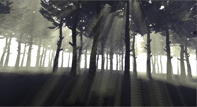
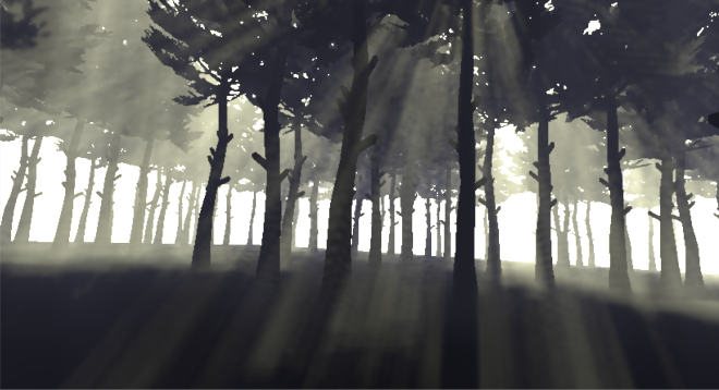
This is the result of this stage using 32 samples per pixel:
There is some aliasing that we can improve with a bit of blurring. But before we do that we can further improve aliasing by using interleaved sampling. Because fog values vary slowly across pixels, we can “spread” the evaluation of the fog colour of a single pixel over a number of pixels:
// Calculate the offsets on the ray according to the interleaved sampling pattern
float2 interleavedPos = fmod( float2(i.pos.x, LowResDepth_TexelSize.w - i.pos.y), GRID_SIZE );
float rayStartOffset = ( interleavedPos.y * GRID_SIZE + interleavedPos.x ) * ( stepSize * GRID_SIZE_SQR_RCP ) ;
currentPos += rayStartOffset * rayDir.xyz;
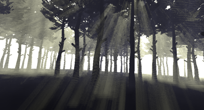
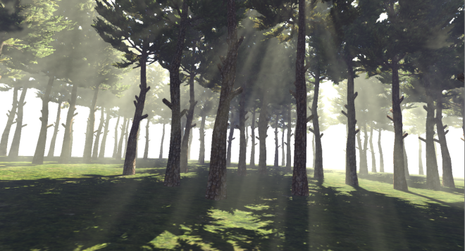
The following image is produced with the same number of 32 samples using 8×8 pixel grids. Each ray starts with an (1/64) * stepSize offset from the previous one providing the equivalent of 64*32 = 2048 “virtual” samples per ray.
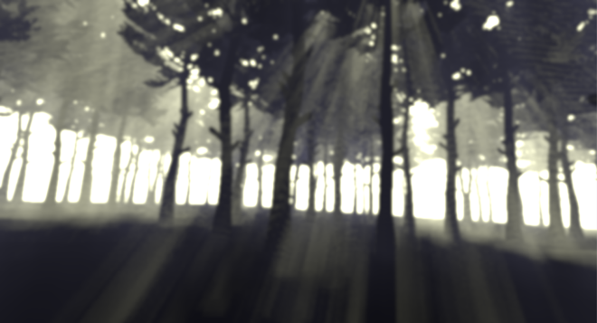
We can improve the fog even further by blurring it. We’ll use a 7-tap Gaussian filter which is separable (meaning it can be applied in 2 passes of a 1×7 and 7×1 kernels instead of a single 7×7 one which is more expensive). 4 passes later, the fog looks much improved:
Only problem is, the naive Gaussian filter will blur the fog over the edges of the geometry giving a fuzzy look to the scene. This can be fixed with bilateral filtering that takes into account depth. The post is getting too long already, so I will refer you to the code for details but to give you an idea of how this works:
float4 frag(v2f input) : SV_Target
{
     const float offset[4] = { 0, 1, 2, 3 };
     const float weight[4] = { 0.266, 0.213, 0.1, 0.036 };

     //linearise depth [0-1]
     float centralDepth = Linear01Depth(tex2D(LowresDepthSampler, input.uv));

     float4 result = tex2D(_MainTex, input.uv) * weight[0];
     float totalWeight = weight[0];

     [unroll]
     for (int i = 1; i < 4; i++)
     {
          float depth = Linear01Depth(tex2D(LowresDepthSampler, (input.uv + BlurDir * offset[i] * _MainTex_TexelSize.xy )));

          float w = abs(depth-centralDepth)* BlurDepthFalloff;
          w = exp(-w*w);

          result += tex2D(_MainTex, ( input.uv + BlurDir * offset[i] * _MainTex_TexelSize.xy )) * w * weight[i];

          totalWeight += w * weight[i];

          depth = Linear01Depth(tex2D(LowresDepthSampler, (input.uv - BlurDir * offset[i] * _MainTex_TexelSize.xy )));

          w = abs(depth-centralDepth)* BlurDepthFalloff;
          w = exp(-w*w);

          result += tex2D(_MainTex, ( input.uv - BlurDir * offset[i] * _MainTex_TexelSize.xy )) * w* weight[i];

          totalWeight += w * weight[i];
     }

return result / totalWeight;
For every sample we sample the depth from the low res depth buffer and compare it to the central pixels depth. We calculate a weight based on an exponential function of this difference and multiply it to the normal gaussian weight. We also accumulate the total weights so as to normalise the result at the end. The larger the depth difference, meaning that we are blurring over an edge, the faster the weight will drop to zero effectively removing the texel’s contribution to the final result.
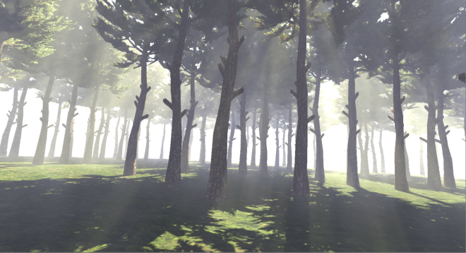
With the improved filter the scene stops being so fuzzy and the geometry edges are preserved:
The final step of our post processing pipeline is to upsample the fog rendertarget and apply it to the main rendertarget. To upsample we will use the Nearest Depth method described here. In short the method compares the low res depths in the neighbourhood of the hi res pixel. If all low res pixels have similar depths with the hi-res one then it upsamples using normal bilinear filtering. Else it picks the value of the one with the closest depth value. Please check the code for an implementation of the method.
Once we have the upsampled fog value we can apply it to the main rendertarget pixel.
float4 frag(v2f input) : SV_Target
{
     float4 fogSample = GetNearestDepthSample(input.uv);

     float4 colourSample = tex2D(_MainTex, input.uv);

     float4 result = colourSample * fogSample.a + fogSample;

     return result;
}
We scale the original pixel value by the alpha channel of the fog value with contains the transmittance which expresses the amount of surface reflected light the reaches the viewer. The thicker the fog the lower the transmittance through it and the less surface light reaches our eyes. The final composite result looks like this:
The advantage of having a non-black shadowed fog colour is that we can easily add fog to shadowed areas, a cheap way to approximate multiple scattering.
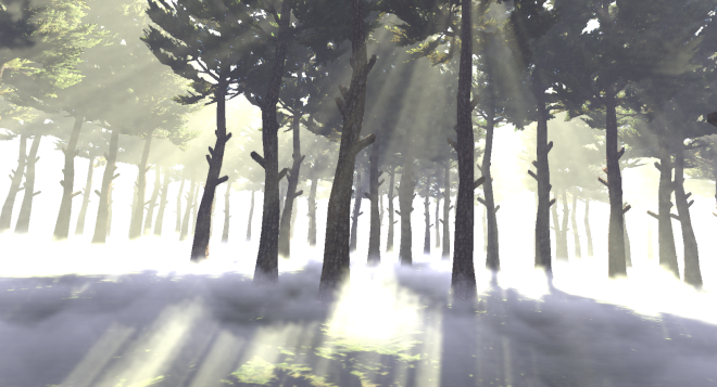
Finally, and I should really stop here, since we are already raymarching the scene we can easily achieve local variations of the fog which can make it more interesting visually. For example if I repurpose the noise texture I used previously as a heightmap and increase the fog density when the sample position is lower than the height in the heightmap:
float2 noiseUV = currentPos.xz / TerrainSize.xz;

//calculate a fog height value for this world position
float fogHeight = 2.5 * saturate( tex2Dlod(NoiseTexture, float4(5*noiseUV + 0.05*_Time.xx, 0, 0)));

float fogDensity =  FogDensity;

//increase fog density if current sample is lower that the fogHeight at this world pos
if( currentPos.y  < fogHeight )
     fogDensity *= 25;
I can easily add low fog to my scene, in addition to the god rays.
You can download the Unity (5.1.1) project and have a play with the code.
I must admit that I enjoyed using Unity to produce the post processing effect. It took me a couple of hours to refamiliarise myself with it and it takes some digging around to find info about more obscure features as the documentation does not seem to cover them, but after a while it became easier.
To come back to my original question of whether the free version of the engine can be used to prototype effects though: now, with the low level graphics access, it absolutely can. It takes some time investment to learn the new low level graphics features exposed with the free version but it is worth the effort.
If you are interested in volumetric fog/atmospheric scattering, better implementations of the method and more theory you can find here:
- Light Transport in Participating Media
- Dynamic volumetric lighting and shadowing with temporal upsampling
- Volumetric Lighting for Many Lights in Lords of the Fallen
- Real-Time Volumetric Rendering
- Volumetric fog: Unified, compute shader based solution to atmospheric scattering
- Atmospheric Light Scattering with a demo and also a Unity implemetation
- And of course on Shadertoy!
Also while I was working on the article I found out that Unity released the code/assets for the Atmospheric scattering system they used for the Blacksmith demo, well worth studying.

Great read! Would this technique work with multiple lights? For example many Point Lights in a foggy night scene.
It could, if you processed the point lights in a forward fashion, i.e. pass them all as constants to the fog pixel shader. A clustered shading approach would probably be more appropriate though as it would make determining the lights that affect each fog sample much easier.
Ok, good to know. I’m still a bit surprised that no publicly available scattering solutions support multiple lights. They all work with a single directional light only.
This approach seems promising: http://robert.cupisz.eu/post/119949491421/volumetricfog
still an early WIP though.
Wish I’d be more proficient in coding to come up with something of my own…
very cool i downloaded the files but its not working with unity 5.3.0f4 could you update your code? any other progress on multiple lights?
Hi Kosta,
im trying to follow the tutorial though i get an error early on thats driving me crazy. I am in the first step of the fog creation but i cant get the shadowmap sampling to compile.
Specifically this line
float shadowTerm = UNITY_SAMPLE_SHADOW(MyShadowMap, shadowCoord);
gives me this error : undeclared identifier ‘samplerMyShadowMap’ at line 123 (on d3d11)
My project is on deffered and dx11 (Unity 5.3.2.p2), and in the scene i have a directional light with realtime shadows with the script that creates the Global shadowmap texture attached to it. If i replace the above line with a hardcoded value the shader compiles and gives me the following result http://i.imgur.com/NyTx1VC.png
Any idea what could be causing this?
Thanks a lot for the write up 🙂
Apologies, apparently the sample does not seem to compile with newer Unity versions, I am not sure what they changed to cause this. Hopefully the basics of the post are transferable though to newer versions.
I am not using Unity regularly enough to keep track of the changes, the Unity forums would be a better place to seek help about shadowmaps and how to access them in code.
I actually figured it out eventually! In the calculate fog shader, instead of declaring MyShadowMap as a sampler2D you declare it as a shadowmap like this:
UNITY_DECLARE_SHADOWMAP(MyShadowMap);
I think that was the only change i had to make, though im not sure since i partly followed the tutorial and partly the final source code.
Good the hear, thanks for sharing!
[…] https://interplayoflight.wordpress.com/2015/07/03/adventures-in-postprocessing-with-unity/ […]
Haven’t tried this yet but looks amazing
Extremely impressive man thank you for this!
God bless your soul for how to access a light’s shadow map.
[…] Unity Volumetric Light Beam – ADVENTURES IN POSTPROCESSING WITH UNITY […]